|
This article was contributed by John Yates.
*
My working life was mostly in education: schools briefly, then further/higher education college.
My introduction to computers came on a Saturday morning maths refresher course at Leicester Polytechnic in the early 1960’s. For one session we were taken into the basement to meet an Elliot 803 monster; armed with a few codes which we punched on tape to try to solve a quadratic equation.
Christmas 1969, I accepted the offer of a fortnight’s introduction to FORTRAN while on a course in London. Coding sheets--punched cards—queue for processing—error messages (or success). Then back at college I used it to do one or two lengthy calculations on the college ICL 1900. My model of the Helmholtz coils (2 15cm coils separated by their radius) trying to calculate off-axis fields at a 1cm grid of points, with coils modelled as 100 sided polygons, occupied the computer for about 3 hours – run on a day when the floor was polished and needed that long to dry!
The college then went up to an ICL 2900 and soon BASIC became the student language. We had no fewer than two teletype terminals to serve our site, so programmes could be entered on keyboard and the punched tapes used to store programmes etc.
One or two A-level Physics practical experiments were modelled, e.g. using the Young’s ‘2-slit’ experiment as explored with the 3cm microwave kit; students could take the key dimensions of the set-up they used and get a computer modelled simulation to compare with their measurements, adding a little interest perhaps.
By now in the mid 1970’s I had included Materials Science to my repertoire and was in the Engineering Department. The engineers were generally frightened of computers, and the computer folk were not prepared to cope with nasty brutish workshop machinery, and I had a happy time starting to link the two.
At this time the pride of the workshop was a numerically controlled (NC) drilling and milling machine, which could drill at a point given X and Y horizontal coordinates, depth given by Z, and slots in X and Y directions, or at the 45 degree angles by moving X and Y axes together. The machine had been on view at the annual Machine and Technology Exhibition, and had a Plessey control. Unfortunately any slight error in programming caused a "fail-safe” operation of plunging at full speed into the workpiece, usually causing breakage of a key element in the machine drive. Financing, ordering, getting the replacement and re-fitting, put the machine out of action for a term, not good for student use. Step one was to write a program with simple dialogue where students could enter dimensions, feed rates, etc and obtain a reliable tape to feed to the brute; Computer-assisted NC.
The head of the Production Engineering section had in mind a student exercise to carve a few letters on a board e.g. for a house nameplate. A team of 3 technician students were assigned the task of designing a typeface – all 26 lower and upper case, numerals and punctuation marks. The control program asked for the width of the board, then the message. This was checked for length, if accepted could be placed L,R, centre or spread to the full width (justified) and soon another line could be entered for the same width, without limit except that the length of tape soon became hard to manage. The standard 30mm/height for lower case characters could be altered within limits (size of milling tools limited smallness) and this became a really useful package. Later an NC lathe also had computer assisted entry for different reasons. This lathe was a precision one, with General Electric controller.
At this time one of my neighbours, an engineer, was developing the use of ultrasonics as a cutting tool. After discussion we agreed an exponential taper would be best to couple the ultrasonic power to the smaller diameter of the cutting head. This was required to give an adequate amplitude of vibration to the cutting blade. Doing the rough cuts was OK, given the equation but the finishing profile relied on the computer to calculate very small steps. Starting at the major diameter, the cut progressed until the deviation from the calculated value was approaching the stated accuracy limits of the lathe. The next step restarted on the curve, and so on. The result felt quite smooth to the touch, and was successfully used by the neighbour on high speed profiling machines, cutting laminate materials, including composite wing panels for aircraft. The program also got used as a workshop exercise for HNC students. Enter a few dimensions, etc. to computer – long tape, happily gobbled up by lathe.
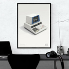
The Commodore PET arrived later; I had an 8k at home and the college had a 16k one that allowed a bit more scope. The output was coupled to the NC machine tape reader with the help of an interface produced by our Electrical Engineering Department. Optical isolation separated the computer from the heavier currents of the NC machine. The computer output had logic 1 as high, 0 as low but the tape reader worked by the pins either feeling paper – 0, or finding a hole to the earthed plate; voltage Low=1, High=0 so the interface included an inverter. (NOT gate?)
Again simple dialogue enabled holes or slots to be done, and if required repeated without re-entry of data, so quite near to the later CNC. Quite soon the computer department decided to abandon the ICL and also move to the other campus, so a more capable Hewlett-Packard desktop was acquired by the Engineering Department and we tried to load the long tape for the letters program onto it. No go. It took nearly a whole morning before we twigged that one computer ended lines with CR, LF and the other with LF,CR. We had to edit every end of line on the tape to the other format before it would load. It did, but we only had another year or so before the NC milling machine was voted obsolete and replaced.
Later the BBC Micro-computer with its greatly improved graphics arrived. The workshop had two Harrison CNC lathes and it was thought we should have the ability to do a ‘dry run’ on the computer to check for serious errors e.g. excessively deep cuts or rapid withdrawal through a wider part of the workpiece. The program was written, given a dry run with an exercise of
1. turning a hemispherical end on a rod; 2. reducing the diameter nearer to the chuck; 3. Finish with a smooth profile, and part-off. It seemed O.K. so a rod was installed, instructions fed to the machine, and it obeyed! Flushed with success, I took the artefact home to show my wife. "So what! Engineers have done that for years.” Total deflation! ---Communication-Zero! Next came a bit of involvement with robots – mostly unsatisfactory toys that came within the educational budget, and one with X,Y and Z moves, singly only, controlled by an internal PET, which could do real work, but not too impressively.
After that computer involvement mainly involved using different software. A term’s secondment to a local engineering company was useful. I was given the task of extending their Production Control System to the raw materials side, - rods, bars, castings. The commercial software was not able to cope with trade practice where steel was ordered by length, but charged by kg. when delivered!
Date : UnknownJohn Yates This exhibit has a reference ID of CH3157. Please quote this reference ID in any communication with the Centre for Computing History. |
|
